Difference between revisions of "HowTo:Configure Dynamic AR Content"
(→Setup) |
(→Setup) |
||
| Line 5: | Line 5: | ||
== Setup == | == Setup == | ||
| − | In order to be able to use the feature properly, a setup folder is required and can be found at the following link [ | + | In order to be able to use the feature properly, a setup folder is required and can be found at the following link [http://wiki.augmensys.com/images/6/66/Dynamic_AR_Content_Folder_Structure.rar FolderStructure]. The setup folder contains: |
# A root folder, named ''UBIK'' | # A root folder, named ''UBIK'' | ||
# The ''UBIK'' root folder contains a child folder, named ''ARConfig'' | # The ''UBIK'' root folder contains a child folder, named ''ARConfig'' | ||
Revision as of 11:00, 5 May 2014
Contents
Introduction
The Dynamic AR Content feature allows the user to see different content according to a marker configuration. The configurable content are 3D objects, movies and UBIK® objects. Currently this feature is enabled for ID Markers and Markerless scanning, meaning image tracking. Therefore, every time the user has scanned an ID marker or a picture, the corresponding object (3D object, movie or UBIK® object) will be processed and, according to the configuration, displayed on the screen.
Setup
In order to be able to use the feature properly, a setup folder is required and can be found at the following link FolderStructure. The setup folder contains:
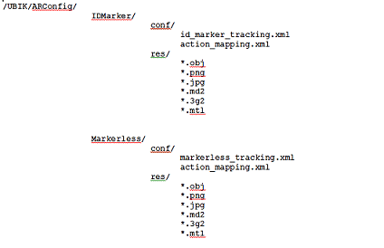
- A root folder, named UBIK
- The UBIK root folder contains a child folder, named ARConfig
- The ARConfig contains two child folders named IDMarker and Markerless
- IDMarker folder contains the resources and configuration files needed for scanning an id marker
- Markerless folder contains the resources and configuration files needed for scanning a picture
- IDMarker and Markerless folder contain a res and a conf folder
- The res folder contains all the resources to be shown, like 3D objects, videos and links to UBIK® objects
- The conf folder contains all the configuration files
The following picture shows an exemplary sketch of the folder structure:
Action Mapping XML Setup
After the folder is configured, the next step is to validate the schema against an online validator. A solution can be found at Online XML Schema Validator. The schema used to validate against can be found inside the UBIK Folder and is named xsd_schema_validation.
The action mapping xml contains different actions such as GeometryAction, MovieAction and UBIKObjectAction.
- The following xml shows an example configuration:
<GeometryAction TrackingID="1">
<GeometryResource>
<ResourcePath>pump.obj</ResourcePath>
<Scale>100</Scale>
</GeometryResource>
</GeometryAction>
<UBIKObjectAction TrackingID="2"/>
<GeometryAction TrackingID="5">
<GeometryResource>
<ResourcePath>pump.obj</ResourcePath>
<Scale>100</Scale>
<RotationDegrees>
<Z>90</Z>
</RotationDegrees>
</GeometryResource>
</GeometryAction>
<UBIKObjectAction TrackingID="6">
<UBIK-UID>a5aa5a70-591f-11e3-949a-0800200c9a66</UBIK-UID>
</UBIKObjectAction>
</TrackingActionMapping>
All Action tags must specify a Tracking id, as an attribute. The Tracking id must exist in the tracking xml.
GeometryAction Tag
Inside the GeometryAction tag there can be a GeometryResource tag that defines the type of resource required for the GeometryAction.
GeometryResource Tag
The GeometryResource contains:
- Resource path: the resource path of the 3D object or video to be displayed.
- Scale: if specified, the 3D object will be scaled to this size.
- OffsetMillimeters: if specified, this value will be added to the position of the detected marker when displaying the 3D object. The offset can be defined along the X, Y and Z axis.
- RotationDegrees. if specified, the 3D object will be rotated by this value against the detected marker.
- Resource path example. pump/pump.obj.
- OffsetMillimeters example.
<X>10</X>
</OffsetMillimeter>
In the following rotation example the user must see the 3d object rotated around X axis and around Z axis 90 degrees. Note that the angle is in radians.
- RotationDegrees example.
<X>0.5707</X>
<Z>0.5705</Z>
</Rotation>
MovieAction Tag
Inside the MovieAction tag there can be two possible resources defined, a MovieResource and a PlayButton resource.
MovieResource
The MovieResource Tag contains the same values as the GeometryResource except the rotation vector.
PlayButton Tag
The PlayButton Tag, if it is defined, contains the same values as the GeometryResource tag. Its purpose is to start a video, if the geometry is touched.
UBIKObjectAction Tag
The UBIKObjectAction tag should enable handling of the UBIK® objects when scanning either a picture or an id marker. The tag must contain the tracking id attribute and, optional, the ubik-uid tag.
- Example. When configuring a tag without the ubik-uid tag the object is searched based on its MarkerID property which is the value inside TrackingID attribute. If the ubik-uid tag exists the object is searched based on the value inside the ubik-uid tag.
Tracking Data XML
The first step is to configure the tracking data xml in order for UBIK® to recognize scanned pictures and id's. In case the marker is a picture (image), the location of the pictures must also be provided. In the example it's ../res/pic_name.(png, jpeg). The id located in the tracking data xml should be the same as the order of the id in the list of ids.
- This example below the configuration of the location of the image:
<SensorCOSID>1</SensorCosID>
<Parameters>
<referenceImage widthMM="420" heightMM="297">../res/img_pic.png</referenceImage>
</Parameters>
</SensorCOS>
Usage
In order to use the previously configured xmls, you can use either the ID Marker activity or the Markerless activity on the UBIK® Android Client.
ID Marker Activity
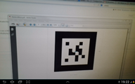
The id markers used can be found at the following link ID Marker Example Ids 1-6.
Having in mind the setup tracking ids, you can now scan id markers.
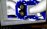
- For an id that has a 3D object mapped in the action xml, the object should be displayed on the screen as shown in the next picture.
- If the id has a video object mapped in the action xml, you should see a video object on the screen, depending on the existence of the play button.
- If the play button exist you should see first see the play button, and after it's clicked the mapped video. If the play button doesn't exist, the movie will be shown immediately.
Markerless Activity
The markerless photos used in this example can be found at the following link Markerless example pictures.
The scenario is very similar with the id marker activity with the only difference that instead of ids you have to scan your tracking images.
Examples
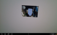
With the existent configuration from the zip file, you should see the following picture when scanning the first id or the first picture:
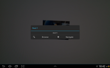
When scanning the second id or the second picture, you should see the following:
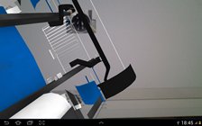
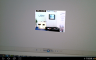
When scanning the sixth id, using the Markerless activity, you should see a play button and, if pressed, a movie.
- Play button:
- Movie:
When scanning the sixth id using the IdMarker Activity you should see a play button also and, if pressed, a movie too.
- Play button:
- Movie:

